If you’ve ever looked at a finished industrial scale and wondered what’s actually going on under the deck, the answer is simpler than it looks. Almost every weighing system comes down to the same handful of building blocks, wired together the same basic way.
The trick isn’t the parts list. It’s getting the selection, the wiring, and the setup right so the whole thing reads accurately and keeps reading accurately for years.
This guide walks you through it from scratch, the components you need, how they wire together, and how to set the system up so it actually works. Keep reading.
What a Load Cell Weighing System Actually Is
A load cell weighing system is a chain reaction. The load cell senses the force. It uses strain gauge technology to detect tiny deformations under load and converts that mechanical strain into a small electrical signal, usually measured in millivolts per volt (mV/V).
That signal then travels down a cable, often through a junction box, and into a display or transmitter that amplifies it, digitizes it and turns it into a weight you can read or send somewhere useful.
Get any link wrong and the number lies to you.
The Core Components You’ll Need
1. Load Cells (the sensor)
This is where it all begins. Choosing the right load cell comes down to three questions:
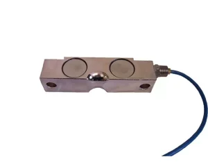
- What type? Single-ended shear beam cells are the workhorses in floor scales and platforms. Double-ended shear beams are better suited to truck and heavy vehicle scales. Then you have compression cells and weigh modules for handling tanks, hoppers and vessels. S-type cells are perfect for tension and suspended loads. And so on.
- What capacity? Add up the maximum live load plus the weight of whatever sits on the cells (the platform, the empty tank, the structure). Then divide that by the number of load cells and add some margin for safety.
A good rule of thumb is to size so your working load lands around 60-80% of capacity. - How many? Most systems use three or four cells. Four is standard for rectangular platforms and tanks because it’s stable and easy to balance.
If you’re not sure how mounting and capacity choices ripple through to real-world accuracy, our breakdown of the factors that affect weighing accuracy is worth a read before you commit.
2. Mounting Hardware or Weigh Modules
Load cells only read accurately when force enters them straight down the measuring axis with nothing giving them a hard time. That’s what mounting hardware is for.
Weigh modules are pre-engineered kits that hold the cell in the right orientation, allow for thermal expansion, and add check rods or bumpers to handle side loads and tipping.
Skip proper mounting and you’ll chase errors forever.
If you want to know more, we go deep on this topic in our guide to rigid and flexible load cell mounting
3. Junction Box and Summing Card
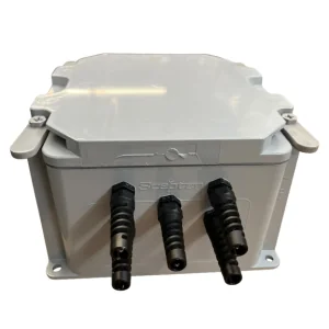
When you’ve got more than one load cell, their signals have to be combined into one before they reach the indicator. That’s the junction box’s job.
Inside a junction box is a summing card that wires the cells in parallel and, on better boards, gives you trim potentiometers. Those trim pots let you “corner balance” the scale so a 100 lb weight reads 100 lb no matter which corner you set it on.
4. Load Cell Cable
Load cell cable is shielded, multi-conductor, and built to keep electrical noise out of a very small signal. Don’t substitute generic wire, and don’t splice it carelessly, because every junction is a chance for noise and corrosion to creep in.
For long distances, or anywhere the signal has to stay clean, six-wire cable earns its keep.
5. Indicator, Transmitter, or Amplifier
A digital weight indicator takes the summed mV/V signal, amplifies it, converts it to a digital value, applies your calibration, and shows the weight.
What you choose depends on where the number needs to go:
- Just need a readout? A standalone indicator with a display does the job.
- Feeding a PLC or control system? You’ll want a transmitter or amplifier that outputs an Analogue or digital signal the PLC can read.
- Batching or process control? A programmable controller with setpoints and relays drives valves, gates, and feeders.
If you’re working towards batching, our post on common batching errors and how to fix them will save you headaches down the line.
6. Power, Displays, and Protection
Tie it all together with a clean power supply, any remote displays or printers your operators need, and surge protection. In outdoor or lightning-prone installations, a lightning arrester on the cable run is a form of insurance against a destroyed indicator.
Wiring It All Together
Load cells use a Wheatstone bridge, and that bridge needs to be wired correctly or the readings drift, jump, or never settle.
4-Wire vs 6-Wire: Know the Difference
A basic load cell uses four wires:
- Excitation + and Excitation – supply voltage to the bridge.
- Signal + and Signal – carry the output back to the indicator.
The problem with four wires is that cable resistance changes with temperature, and that resistance sits right in the excitation path. On long runs or in environments that swing hot and cold, that shows up as span drift.
Six-wire cable fixes it by adding two sense leads. The sense wires let the indicator measure the actual voltage arriving at the cell and compensate automatically. For short indoor runs, four wires are fine. For long runs, outdoor sites, or anywhere temperature moves, go with six.
A Word on Color Codes
Wire colors are not universal. Excitation, signal, and sense leads use different color conventions depending on the manufacturer. Always wire to the calibration certificate or wiring diagram that shipped with your specific cell, not from memory or a generic chart.
Wiring the Junction Box
When you bring multiple cells into the junction box, you wire them in parallel, all the excitation positives together, all the signal positives together, and so on, onto the summing card. Then a single home-run cable carries the combined signal to the indicator.
Grounding and Shielding (don’t skip this)
The cable shield protects your tiny signal from electrical noise, but only if it’s grounded at one end only, typically at the indicator.
Ground it at both ends and you create a ground loop that injects the very noise you were trying to block.
Setting Up and Calibrating the System
Hardware installed and wired? Now you make it accurate. Don’t skip steps here, this is the part that separates a scale you can trust from a number generator.
| Step | What to Do | Why It Matters |
| 1. Mechanical check | Confirm the structure is level, all cells share the load, and nothing binds. Check that check rods and bumper bolts have proper clearance, no contact at rest. | A binding cell or a touching bumper bolt steals load and ruins accuracy before you even power on. |
| 2. Power up and warm up | Energize the indicator and let the system stabilize. | Electronics drift slightly when cold; a warm-up gives you a stable baseline. |
| 3. Corner / section trim | Place a known weight over each cell in turn. Adjust the junction box trim pots until every corner reads the same. | A weight should read identically no matter where it sits on the platform. |
| 4. Zero the system | With the platform empty, set the indicator to zero (dead load calibration). | This tells the system what “nothing” weighs, tank, platform, and all. |
| 5. Span calibration | Apply a known certified test weight near full capacity and set the indicator to match. | This sets the slope, so every reading in between lands correctly. |
| 6. Linearity check | Test several points across the range, not just zero and span. | Catches non-linear behavior a two-point calibration would hide. |
| 7. Verify and document | Re-test with known weights, record results, and label the installation. | Your proof the system is accurate, and your baseline for future checks. |
After that, the system isn’t “done”, it needs periodic recalibration, especially after an overload event or any mechanical change. Build that into your maintenance schedule from day one to avoid downtime and increase the life-time of your system.
Build It Right with Massload
A load cell weighing system isn’t complicated once you see the chain, sensor, mounting, junction box, cable, indicator, set up well and calibrated with discipline. Get each link right and you get a number you can trust.
If you’d rather not guess on capacity, cell type, or system architecture, that’s what we’re here for.
Talk to Massload’s experts and we’ll help you spec a system that matches your application, your environment and your accuracy requirements.