October 27, 2026
A load cell’s raw output is a few millivolts. Before your controller can use it, something has to supply excitation voltage, amplify the load cell output signal, and convert it into voltage output, current output, or displayed value.
In a one-off scale, that job goes to an off-the-shelf indicator. In a machine you build by the hundred, where that electronics sits becomes a design decision with real consequences for cost, noise, service, and size.
The short answer: you have three places to put load cell signal conditioning: inside the load cell, close to it in the machine, or back in the control panel.
Embedding it inside the cell gives the cleanest signal and the simplest wiring. Panel mounting is the easiest to service and swap.
Near-sensor modules sit in between. The right choice depends on cable length, electrical noise, how many cells you have, and who will service the machine in the field.
This guide compares the three options, then walks through the design checks that apply to all of them.
If the mV/V signal itself is new to you, start with our introductory guide to mV/V.
Option 1: Inside the load cell
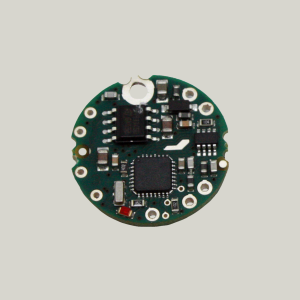
Embedded signal conditioners are small enough to fit inside a load cell or transducer body. The boards in our ICA family, for example, are 19.5 mm across and 7.6 mm tall. With one fitted, the cell delivers a conditioned output, such as 0–10 V, 4–20 mA, or a digital bus, instead of millivolts.
- Cleanest signal: The millivolt run from the strain gauges to the amplifier is a few centimetres, so there is almost no cable to pick up interference from motors and drives.
- Simplest wiring for your customer: The cell plugs straight into a PLC input or bus, with no separate box to mount or wire.
- Calibrated as one unit: Sensor and electronics are matched and calibrated together, so the output arrives scaled.
- The trade-offs: The board lives in the cell’s environment: its temperature, shock, vibration, and washdown. A failed board usually means replacing or reworking the whole cell. And once each cell has its own amplified output, you can no longer sum several cells in a junction box.
Option 2: Close to the cell, in your own enclosure
The same small boards and modules can sit in an enclosure you design into the machine, a short cable run from a standard mV/V cell. Some are made for this: the ICA boards can go in an optional stainless field enclosure rated IP67, and our ML 4-20MA Signal Conditioner is built to mount in a load cell housing or a nearby enclosure.
- Short millivolt run, standard cell: You get most of the noise benefit without modifying the sensor.
- Electronics you can replace separately: A failed module is a board swap, not a new load cell.
- Your enclosure, your responsibility: Sealing, cable glands, grounding, and EMC shielding are now part of your design.
Option 3: In the control panel
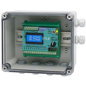
The traditional approach keeps the load cell as a pure mV/V sensor and puts the conditioning in the panel, on a DIN rail or in a transmitter. The LCD20 DIN-rail conditioner, the SGA, and our load cell transmitters all work this way.
- Easiest to service: Electronics live in a clean, dry cabinet where technicians expect to find them.
- Multi-cell friendly: Several cells can be summed in a junction box and read by one conditioner.
- The trade-off is the cable: The full millivolt run goes from cell to panel, so cable quality, routing and grounding decide how much noise reaches the reading.
The three options compared
|
Inside the cell |
Near the cell |
In the panel |
|
|
Millivolt cable run |
Not applicable |
Short |
Full distance to the panel |
|
Noise immunity |
Best |
Very good |
Very good to good, depends on cable and routing |
|
Standard load cell |
No, the cell is modified |
Yes |
Yes |
|
Electronics environment |
Same as the cell |
Your enclosure |
Control cabinet |
|
Field service |
Replace the cell |
Replace the module |
Replace the module |
|
Junction-box summing |
No |
No |
Yes |
|
Typical fit |
High-volume machines, compact sensors, digital networks |
Mobile and outdoor machines, retrofits |
Multi-cell scales, panels with existing PLC I/O |
Matching the output to your controller
Wherever the electronics sit, the output has to match what your controller reads. Our comparison of load cell output types covers the trade-offs between mV/V, 4–20 mA and 0–10 V in depth; here is how that choice maps to embedded options.
|
Your controller or network |
Output to choose |
Embedded examples |
|
PLC or DAQ voltage input |
0–10 V or 0–5 V |
ICA1H (0.1–10.1 V), ICA2H (0.1–5.1 V) |
|
Force that reverses: tension and compression |
Bipolar ±10 V |
ICA3H, ICA6H |
|
PLC current input, long or noisy runs |
4–20 mA |
ICA4H (3-wire), ICA5S (2-wire loop-powered) |
|
Hazardous area |
Intrinsically safe 4–20 mA |
|
|
Several sensors on one cable, or vehicle networks |
RS-485, Modbus or CAN (J1939) |
Two cases deserve a closer look on machines:
Bipolar outputs matter whenever force can change direction, such as a cylinder that pushes and pulls or a link that sees tension and compression. A unipolar 0–10 V output cannot represent the reverse direction, so pick a ±10 V board from the start.
Digital buses change the economics of multi-sensor machines. The DCell puts up to 32 sensors on a single 4-wire bus, with cable runs up to 1,000 m, and handles linearization and temperature compensation on the board. CAN with J1939 suits mobile equipment that already runs a vehicle network. Our primer on digital load cells covers the wider picture.
Design checks before you commit
Whichever option you choose, these are the checks that decide whether it works on the production floor.
- Supply voltage: Match the board to your machine’s rail. A 24 V industrial supply suits most boards; a 12 V vehicle system does not suit them all. The ICA1H needs 13 to 28 VDC, while the ICA2H runs from 8.5 VDC and the DCell from 5.6 VDC.
- Excitation and bridge match: Embedded boards often excite the bridge at 5 V rather than the 10 V a panel indicator might use, which halves the raw signal. Check that the cell’s rated output falls inside the board’s bridge sensitivity range and that its bridge resistance is supported. Our guide to how to read a load cell datasheet explains both rows.
- Cable runs: Keep any millivolt run as short as possible, use shielded load cell cables, and route them away from motor and drive power cables.
- Environment: Check the electronics’ rating as carefully as the cell’s. The ICA and DCell boards are rated from −40°C to +85°C. Inside a cell or a sealed enclosure they also need protection from moisture, shock and vibration.
- Update rate: Dynamic jobs need fast readings. The DCell delivers 500 readings per second, which suits conveyors, sorting lines and packaging machines. Confirm the rate your process needs before choosing.
- Calibration and spares: Decide how the system is calibrated in production and how a field technician replaces a failed sensor. If the cell and board are calibrated as a pair, the spare is the pair.
Most weighing problems in OEM machines come from the installation, not the sensor; our guide to real-world weighing accuracy covers the rest of that list.
Massload options at each level
Our standard load cells are supplied as mV/V sensors, and our signal conditioners cover every placement option from there:
|
Where it sits |
Products |
Output |
|
Inside the sensor body |
ICA family (seven variants), DCell |
0–5 V, 0–10 V, ±10 V, 4–20 mA, or RS-485 / Modbus / CAN |
|
Close to the cell |
ICA in its IP67 field enclosure, ML 4-20MA |
Voltage or 4–20 mA |
|
In the panel |
LCD20 DIN-rail conditioner, SGA, TLB, TLE, TLS, load cell transmitters. |
Analog, and fieldbus / Modbus on transmitters |
Choosing the right level for your machine
If you build many identical machines, need a compact sensor or already run a digital network, embedding the electronics in or next to the cell usually pays off.
If your machine has several cells feeding one reading, long but well-shielded cable runs or field technicians who expect a panel, keep the cell as mV/V and condition the signal in the cabinet.
If you would like a second opinion on which approach fits your design, talk to our team.
Frequently asked questions
What is an embedded load cell signal conditioner?
A small circuit board that fits inside a load cell or sits right beside it. It supplies excitation to the strain gauges and turns the millivolt signal into a voltage, current or digital output that a controller can read directly.
Is an embedded conditioner more accurate than a panel-mounted one?
Not necessarily, but it is usually cleaner in noisy machines. With only centimetres of millivolt cable, there is far less opportunity for interference from motors and drives to reach the reading.
Can I connect several embedded load cells to one controller?
Yes. Analog outputs each need their own controller input. A digital bus such as RS-485 or CAN can carry many sensors on one cable; the DCell supports up to 32 on a single 4-wire bus.
Can I still sum load cells in a junction box if they have embedded electronics?
No. Junction-box summing only works with raw mV/V signals. With amplified outputs, combine the readings in the controller instead.
What supply voltage do embedded signal conditioners need?
It varies by model, check the board against your machine’s supply rail early, especially on 12 V vehicle systems.