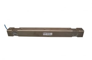
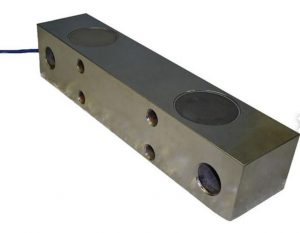
A load cell datasheet packs a lot of specifications into a small table, and most of them are written for people who already know what they mean.
If you are comparing cells for a new scale, replacing a failed sensor, or checking whether a cell will survive on the job site, you need to know which rows decide the outcome and which are background noise.
This guide walks through a typical datasheet row by row. We group the specs the way most sheets do: capacity and mechanical limits, electrical characteristics, accuracy and performance, and environmental ratings; and for each one we explain what it means, what a typical value looks like and when it should change your decision.
If terms like mV/V are new to you, our introductory guide to mV/V is the place to start. If you are trying to make sense of the signal coming out of a cell that is already installed, see how to read load cell output signals. This article is about the sheet itself.
The four sections of every load cell datasheet
Layouts vary by manufacturer, but the information almost always falls into four groups:
- Capacity and mechanical limits tell you how much load the cell measures and how much it can survive.
- Electrical characteristics tell you what the cell needs from your instrumentation and what it sends back.
- Accuracy and performance tell you how faithfully the output tracks the real load.
- Environmental ratings tell you where the cell can live.
Capacity and mechanical limits
Rated capacity
Is the maximum load the cell is designed to measure within its stated accuracy. It is quoted in pounds, kilograms, newtons, or tonnes, and it is the first number to get right.
Choose a capacity higher than the heaviest load you expect to see, including the dead weight of the platform, hopper or vessel sitting on the cell.
A common rule of thumb is to size so that your maximum expected load lands somewhere between about 50% to 75% of load cell capacity. Too low and you risk overload; too high and you throw away resolution.
Safe overload
Is the capacity the load the cell can tolerate without a permanent shift in its performance.
This is your margin for accidental over-filling, a forklift bumping the platform or a snatched lift. It is not a second capacity rating, and repeated excursions into this zone shorten a load cell’s life.
Ultimate overload
Is the load at which the cell may fail structurally. Between safe and ultimate overload, the cell is probably damaged; beyond ultimate, it may break.
When a cell sits in a lifting path, this number is a safety figure, not a performance one, and it is one reason crane and lifting load cells are often sized with much larger headroom than a static floor scale.
Side load and eccentric load limits
They tell you how much off-axis force the cell tolerates. Datasheets for beam and canister cells sometimes omit these because they assume a proper mount that keeps the load vertical.
Deflection at rated capacity
Is how far the cell’s loading point moves under full load, usually a fraction of a millimetre for beam and canister cells and a little more for S-type and single-point designs.
It sounds like trivia until you design the structure around the cell: a vessel on four cells that each deflect 0.3 mm will tilt if the loads are uneven, a conveyor frame needs enough clearance to let the cell move, and a rigid mount that fights that movement will put the error straight back into the reading.
Check this row whenever the cell sits inside a frame, a weigh module or an OEM machine rather than under a free-standing platform.
Electrical characteristics
Rated output
Is also written as FS, full scale output, FSO, or sensitivity.
It’s the signal the cell produces at rated capacity, expressed in millivolts per volt of excitation.
Multiply by your excitation voltage to get the actual signal: a 2 mV/V cell at 10 V excitation gives about 20 mV at full load.
The tolerance beside it (±0.25% FS on both cells) tells you how far a given unit may sit from the nominal figure, which matters when you are matching several cells under one platform, because mismatched outputs put uneven weight on the corners.
Excitation voltage
Is the supply the cell needs across its bridge. Sheets list either a recommended value, a range, or a maximum.
Exceeding the maximum heats the strain gauges and drifts the reading; the indicator or transmitter you pair the cell with must sit inside this limit.
Input and output resistance
Are the resistances measured across the excitation pair and the signal pair. Standard bridges are 350 Ω or 700 Ω, sometimes 1,000 Ω or higher.
Two practical uses: first, a quick multimeter check against the datasheet value tells you whether a cell in the field is damaged; second, the input resistance decides how many cells your indicator can drive. Four 350 Ω cells in parallel present about 88 Ω to the excitation supply, which some indicators cannot handle. Four 700 Ω cells present about 175 Ω, which is one reason higher-resistance bridges are common on multi-cell truck and floor scales.
Check your indicator’s minimum load resistance before you finalize the count.
Zero balance
Is the small signal a cell puts out with no load applied, quoted as a percentage of rated output (often within ±1% FS). It is normal and gets tared out at the indicator; what matters is that it stays put.
A zero balance that has wandered far from the datasheet value after a few years in service is a sign of overload or moisture ingress.
Insulation resistance
Is the resistance between the bridge circuit and the cell body, typically quoted in the thousands of megohms. Low insulation resistance in a used cell almost always means moisture has got in, and it is the first thing to test when a scale starts drifting after washdown or rain.
Wiring and cable
They tell you the colour code for excitation, signal and sense lines, the cable length and jacket material. A common four-wire convention is red for excitation positive, black for excitation negative, green for signal positive and white for signal negative, with a bare or braided shield, but the colour code is not universal across manufacturers and six-wire cells add a pair of sense lines, so keep the sheet handy when you land wires in a junction box.
Our guide to how to build a weighing system covers the wiring side in detail.
Accuracy and performance
This is the section buyers spend the most time on, and it is also the one where the “% FS” convention matters most. Every figure below is a fraction of full scale, so a cell rated ± 0.05% FS non-linearity has the same absolute error at 10% load as at 100% load.
On a 25,000 lb cell, ± 0.05% FS is ±12.5 lb everywhere in the range, which is a fine spec at full load and a very different story if you are routinely weighing 500 lb on it. That is the second reason to size capacity carefully.
Non-linearity
Is the maximum deviation of the output from a straight line drawn between zero and full scale, measured on increasing load. Values from about ± 0.02% to ± 0.1% FS cover most industrial cells; process-control and lab cells sit at the tight end, rugged lifting and vehicle-weighing cells at the looser end.
Hysteresis
Is the difference between the output at a given load on the way up and the output at the same load on the way down.
It comes from the mechanical behaviour of the sensing element and is usually of the same order as non-linearity. Hysteresis is worth a second look for applications where the load cycles constantly, such as check-weighing or filling, and it is one reason a cell with excellent non-linearity can still disappoint in a batching system.
Our guide to common batching errors shows where this turns up in practice.
Repeatability (sometimes non-repeatability)
Is how closely the cell returns the same output for the same load applied several times under the same conditions.
For most weighing tasks this is the accuracy figure that matters most day to day: a cell that reads slightly wrong but reads consistently wrong can be calibrated; a cell that scatters cannot.
Creep
Is the change in output over time under a constant load, typically quoted over 20 or 30 minutes as a percentage of the applied load.
Creep recovery is the mirror image: how far the zero reading is off after that load is removed.
Creep matters for static weighing where the load sits for a long time, like silo and tank inventory, and matters much less for a truck that rolls on and off in thirty seconds.
Combined error
Rolls the individual accuracy figures into one number and is the single most useful row for comparing cells from different makers, provided both sheets define it the same way.
Some manufacturers quote the maximum deviation from the ideal line measured on both increasing and decreasing load, which captures non-linearity and hysteresis together. Others calculate it as the root-sum-square of non-linearity, hysteresis and repeatability, which gives a smaller figure than simply adding the three.
Where combined error is missing, adding non-linearity and hysteresis gives a conservative estimate; where two sheets show very different combined errors but similar individual figures, check which method each one used before concluding one cell is better.
Temperature effect on zero and temperature effect on output (or span)
Tell you how much the zero reading and the sensitivity shift per degree of temperature change, quoted as % FS per °C or per 10°C. These are small numbers on paper, but they scale with temperature swing.
A cell with a zero shift of 0.002% FS per °C that sees a 30°C swing between a winter morning and a summer afternoon will drift 0.06% FS at zero, which can exceed its entire non-linearity budget.
If your scale lives outdoors or in an unheated building, these two rows deserve as much attention as non-linearity.
Environmental ratings
Compensated temperature range
Is the band across which the manufacturer has actively compensated the cell so that the accuracy specs hold.
Inside this range, the datasheet accuracy applies; outside it, the cell still works but the temperature effects above are no longer guaranteed.
Operating temperature range
Is the wider band across which the cell will function without damage — −40°C to +80°C on both cells. The gap between the two ranges is important and easy to miss: a cell that is “rated to −40°C” may only be accurate down to −10°C.
For a Canadian outdoor installation, ask for the compensated range, not the operating range, and plan for periodic recalibration if the site spends months below it.
Sealing standard (IP rating)
Describes protection against dust and water using the two-digit IP code. The first digit covers solid, the second liquids.
IP67 means dust-tight and protected against temporary immersion. IP68 adds continuous immersion and is the usual choice for washdown, marine, and buried or flooded installations. Cells with IP65 or lower belong indoors.
Note that the rating describes the cell body; the cable entry and the junction box have their own ratings and are usually the weak point.
Material and coating
Tell you what the cell is made of and how it is protected. Alloy steel with a nickel plating is the industrial workhorse: high strength, good fatigue life, protected against ordinary corrosion.
Stainless steel resists chemicals and washdown but is typically a little less stiff, so stainless cells sometimes carry slightly looser accuracy specs at the same capacity.
Hermetically welded stainless cells combine the material with the sealing and are the default for food, pharmaceutical and chemical plants.
Hazardous area approvals
Where listed, indicate the cell has been certified for use in explosive atmospheres, usually alongside an intrinsically safe barrier. If your site has a classified zone, the approval on the sheet needs to match the zone classification your safety plan calls for.
Approvals and certifications
The last rows of most datasheets list third-party approvals, and it is worth being clear about what each one certifies.
Legal-for-trade approvals
In Canada – Measurement Canada; in the United States – NTEP; internationally – OIML. They certify that the cell has been evaluated for use in scales that determine a price or a fee.
If you are selling by weight, your cell must carry the appropriate approval and the sheet will show its accuracy class and the maximum number of verification intervals it supports. If you are weighing for process control, inventory or overload protection, these approvals are not required, and cells without them are often a better fit.
Calibration certifications
They tell you the cell’s as-built performance has been verified against traceable standards. Massload’s VCAP certification is a Canadian program of this kind, and it is one reason our cells arrive with performance documentation rather than just a nominal spec.
Which specs actually matter for your application
Not every row deserves equal weight. Here is where we would start for four common situations:
|
Application |
Read first |
Read second |
Usually secondary |
|
Truck, axle or vehicle scale |
Capacity, safe overload, compensated temp range |
IP rating, input resistance (multi-cell) |
Creep, hysteresis |
|
Batching, filling, check-weighing |
Non-linearity, hysteresis, repeatability |
Rated output tolerance (cell matching) |
Ultimate overload |
|
Silo, tank, hopper inventory |
Creep, temperature effect on zero, capacity incl. dead load |
IP rating, material |
Hysteresis |
|
Crane, lifting, tension |
Ultimate overload, safe overload, material |
Compensated temp range, IP rating |
Creep |
The pattern is simple: dynamic, cycling loads push you toward the accuracy section; static, long-duration loads push you toward creep and temperature; anything in a lifting path pushes you toward the overload rows first.
Frequently asked questions
What does % FS mean on a load cell datasheet?
Percentage of full scale. The figure is a fraction of the cell’s rated capacity or rated output, so it represents the same absolute error at any load. A ± 0.05% FS spec on a 25,000 lb cell is ± 12.5 lb whether you are weighing 1,000 lb or 25,000 lb.
What is the difference between safe overload and ultimate overload?
Safe overload (commonly 150% FS) is the load the cell survives without a permanent performance shift. Ultimate overload (commonly 200–300% FS) is the load at which it may break. Between the two, assume the cell is damaged and needs recalibration or replacement.
Why are input and output resistance different on some datasheets?
Manufacturers sometimes add trim resistors to the excitation side for temperature compensation, which raises the input resistance above the bare bridge value. The output resistance is closer to the bridge itself. Both are useful for field checks; the input value is the one that determines how many cells an indicator can drive.
Does a higher mV/V rating mean a more accurate load cell?
No. Rated output is signal strength, not accuracy. A 3 mV/V cell gives a larger signal than a 2 mV/V cell at the same excitation, which can help with resolution and noise immunity, but its accuracy is set by non-linearity, hysteresis, repeatability and temperature effects.
Reading the sheet is step one
A datasheet tells you what a cell can do under test conditions; the mount, the cable run, the junction box and the indicator decide what it does on your site.
Every load cell on our site lists its full specification table, and if you would like a second opinion on which rows matter for your installation (or you have a competitor’s sheet you want compared line by line), talk to our team.
Massload has been building and calibrating load cells since 1981, and translating spec sheets into working scales is most of what we do.